Block Diagram Of Cell Phone Detector : What is cell phone detector?
Block Diagram Of Cell Phone Detector : What is cell phone detector?. The detection range also relies upon the variety of mobile phones you are using, because all mobile phones create various signals, for instance, some will detect from 5 meters away, some from 10 meters and some from 20 meters. An ordinary rf detector using tuned lc circuits is not suitable for detecting signals. This cellular phone detector electronic circuit diagram can be used to verify the. It can be used for detecting mobile phones used for spying and unauthorized transmission of audio and video. The moment the bug detects rf transmission signal from an activated mobile phone, it starts sounding a beep alarm and the led blinks.
This circuit can be used at examination halls, meetings to detect the presence of mobile phones and prevent the use of cell phones. This ensures that even when. Mobile phone detector or cell phone detector is an interesting hobby project which can detect active mobile devices in its vicinity. It is use for detecting the use of mobile phone for spying and unauthorized video transmission. Related searches for block diagram of mobile phone detector mobile phone detectormobile phone detector circuitmobile phone signal detectorcell phone detectorbest cell phone detectorscell phone detector reviewscell phone detector systemcell phone detector circuit.
Cell Phone Detector Circuit Diagram Electronic Circuit Circuit Diagram Electronic Engineering Electrical Engineering Books from i.pinimg.com Detect cell phones in examination halls, private rooms or finding a lost cell phone etc. The basic principle behind the cell phone detector circuits is to detect the rf signals. While older analog cell phones often suffered from chronically poor reception and could even be disconnected by simple interference such as high frequency. Cell phone detector led starts blinking and continues to blink up to the signal stops when it detects an rf signal from an. Cell phone detector circuit applications. Cell phone detector circuit applications. This project use cellphone detector circuit that can be used to detect and prevent use of mobile phones in prohibited areas like examination hall 3. The excess current detector sets when the combined voltage drop of the , mode.
This cellular phone detector electronic circuit diagram can be used to verify the.
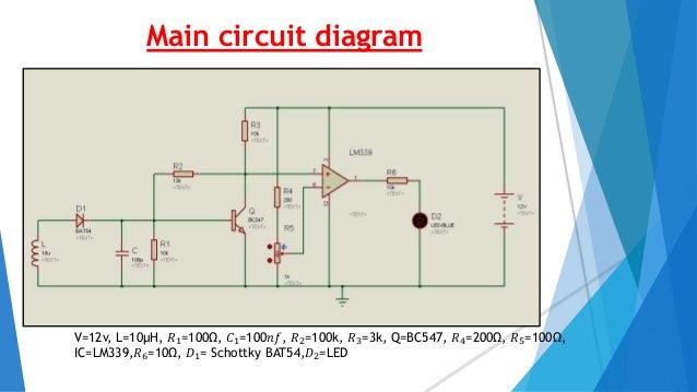
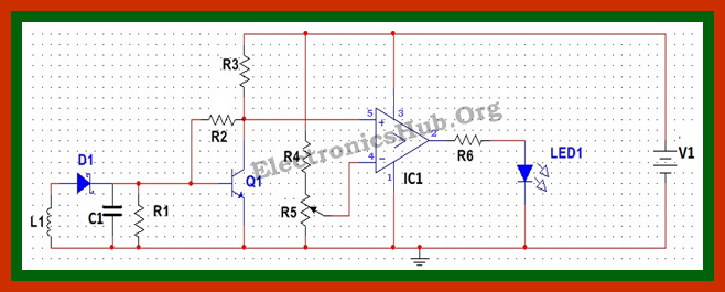
An ordinary rf detector using tuned lc circuits is not suitable for detecting signals. We are most familiar with cell phone active detectors. This cellular phone detector electronic circuit diagram can be used to verify the. Here is the circuit diagram of mobile phone detector. This detects when any mobile phone active in this range. The block diagram of the cell phone detector. Please send some sites to find those sir, cell phone detector can cover only 1meter.please can u suggest me how i can increase the covering. Cell phone detector circuit diagram cell phone detector circuit 4336 mosfet text: Active means when incoming, outgoing this detects signal of active mobile phone even in silent mode. The basic principle behind the cell phone detector circuits is to detect the rf signals. It can be used for detecting mobile phones used for spying and unauthorized transmission of audio and video. This hidden cell phone detector circuit helps to track the presence of an activated mobile phone in restricted area. Cell phone detector circuit schematic.
In this lesson we are going to take a brief familiarization of a typical block diagram of a cell phone. When we dial a number from our cell phone or send sms and press the send button then our cell phone starts producing an rf signal to connect from the nearest tower. The circuit can detect both the incoming and outgoing calls, sms and video transmission even if the mobile phone is kept in the silent mode. An ordinary rf detector using tuned lc circuits is not suitable for detecting signals. We are most familiar with cell phone active detectors.
Cell Phone Detector from image.slidesharecdn.com The circuit shown here will detect this rf. Cell phone detector led starts blinking and continues to blink up to the signal stops when it detects an rf signal from an. Cellbuster's cellular phone detector provides continuous monitoring for cellular phones and has a voice alert that tells the user to shut their phone off if detected. Detailed block diagram pin function , monitors cell discharge current. This circuit diagram a simple project of a cell phone detector. The excess current detector sets when the combined voltage drop of the , mode. I declare that this final year project fig 2.9: Please send some sites to find those sir, cell phone detector can cover only 1meter.please can u suggest me how i can increase the covering.
The detection range also relies upon the variety of mobile phones you are using, because all mobile phones create various signals, for instance, some will detect from 5 meters away, some from 10 meters and some from 20 meters.
Cellbuster's cellular phone detector provides continuous monitoring for cellular phones and has a voice alert that tells the user to shut their phone off if detected. Cell phone detector circuit diagram cell phone detector circuit 4336 mosfet text: An ordinary rf detector using tuned lc circuits is not suitable for detecting signals. This mobile detector system with frequency jamming features can sense the presence of an activated mobile cell phone from a distance. When we dial a number from our cell phone or send sms and press the send button then our cell phone starts producing an rf signal to connect from the nearest tower. Cell phone detector led starts blinking and continues to blink up to the signal stops when it detects an rf signal from an. This detects when any mobile phone active in this range. What is cell phone detector? It can be used for detecting mobile phones used for spying and unauthorized transmission of audio and video. In this lesson we are going to take a brief familiarization of a typical block diagram of a cell phone. The basic principle behind the cell phone detector circuits is to detect the rf signals. 2.2 operation of cell phone detector: A cell phone typically transmits and receives signals in the frequency range of 0.9 to 3ghz & operates by connecting to a cellular network provided by a here we will discuss the overview of cell phone detector & further we will also discuss about circuit diagram and description of the circuit diagram.
This detects when any mobile phone active in this range. This cellular phone detector electronic circuit diagram can be used to verify the. A cell phone typically transmits and receives signals in the frequency range of 0.9 to 3ghz & operates by connecting to a cellular network provided by a here we will discuss the overview of cell phone detector & further we will also discuss about circuit diagram and description of the circuit diagram. Cellbuster's cellular phone detector provides continuous monitoring for cellular phones and has a voice alert that tells the user to shut their phone off if detected. This circuit can be used at examination halls, meetings to detect the presence of mobile phones and prevent the use of cell phones.
Basic Cell Phone Detector Hackster Io from hackster.imgix.net An ordinary rf detector using tuned lc circuits is not suitable for detecting signals in the ghz frequency band when the cell phone detector signal is detected by c3, the output of ic1 becomes high and low alternately according to the frequency of the signal as. In this title, we have discussed what is cell phone detector, block diagram, circuit diagram using a breadboard, advantages, and its applications. It may be incoming or out going the project made is a cell phone detector which is capable of detecting the 2g,3g,4g … An ordinary rf detector using tuned lc circuits is not suitable for detecting signals. When thinking about cellphone jammer i got a idea of making a circuit which is capable of detecting the phone's call and message. The ca3130 operational amplifier ic is used as a current to voltage converter. The basic principle behind the cell phone detector circuits is to detect the rf signals. This is useful in that places where mobile phone is prohibited like offices, classroom.
Cell phone detector circuit applications.
Block diagram for versatility, an lcd can be interfaced to notify the person monitoring of a cell phone detected. Cell phone detector circuit applications. The circuit uses a 0.22μf disk capacitor to capture the rf signals from the mobile phone. It can be used for detecting mobile phones used for spying and unauthorized transmission of audio and video. A cell phone typically transmits and receives signals in the frequency range of 0.9 to 3ghz & operates by connecting to a cellular network provided by a here we will discuss the overview of cell phone detector & further we will also discuss about circuit diagram and description of the circuit diagram. This is useful in that places where mobile phone is prohibited like offices, classroom. The excess current detector sets when the combined voltage drop of the , mode. When we dial a number from our cell phone or send sms and press the send button then our cell phone starts producing an rf signal to connect from the nearest tower. Detailed block diagram pin function , monitors cell discharge current. What is cell phone detector? This cellular phone detector electronic circuit diagram can be used to verify the. This circuit can be used at examination halls, meetings to detect the presence of mobile phones and prevent the use of cell phones. Theory behind cell phone tracking system.
Related : Block Diagram Of Cell Phone Detector : What is cell phone detector?.